Rapid Prototyping
Rapid Prototyping
Rapid Prototyping
Rapid prototyping is a family of technologies that permit fast, efficient, and cost-effective iterations of a proposed design. In some cases these technologies are suitable for low to medium volume production. Various methods of 3D printing are a major part of rapid prototyping, but CNC machining, laser cutting, and other quick material forming technologies are also significant.
See our rapid prototyping resources and other relevant workshop equipment.
Rapid prototyping is a family of technologies that permit fast, efficient, and cost-effective iterations of a proposed design. In some cases these technologies are suitable for low to medium volume production. Various methods of 3D printing are a major part of rapid prototyping, but CNC machining, laser cutting, and other quick material forming technologies are also significant.
<See our rapid prototyping resources and other relevant workshop equipment.
Rapid prototyping is a family of technologies that permit fast, efficient, and cost-effective iterations of a proposed design. In some cases these technologies are suitable for low to medium volume production. Various methods of 3D printing are a major part of rapid prototyping, but CNC machining, laser cutting, and other quick material forming technologies are also significant.
See our rapid prototyping resources and other relevant workshop equipment.
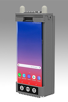
Prototype Radio Handset
This handset prototype was developed for use in challenging radio environments. Several projects made use of this general design, mostly for military and secure monitoring purposes.
The mechanical design of this handset was done in close collaboration with the electronics design team, where circuit board and antenna dimensions and placement were critical to the performance of the system. The entire back of the handset comprises a flat battery pack, and the design work included power management, battery attachment, and battery charging considerations.
Numerous versions of the handset enclosure and battery pack were prototyped and assembled using 3D printing with an extremely tough resin. For some versions, LED light guides were printed in a clear resin. Carbon fiber sheet was also used, and CNC milled to final dimensions. Some parts were CNC milled from aluminum, including the heatsinks and some internal structural components.
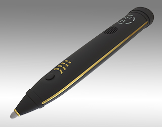
Handheld Device for the Health & Wellness Industry
This proof-of-concept prototype incorporated 3D printing, casting, plating, CNC milling, and lathe turning. Parts were printed in black resin for the main body, and clear for the LED light guides. Internal sealing elements were printed in elastic resin. Parts were printed in castable wax for cast metal parts, which after casting and finishing were polished and gold plated. Prototype pc boards for fit and initial function testing were CNC milled. The tip holder was lathe turned.
Other rapid prototyping included printing an oval bobbin for an internal wireless charging circuit, winding the bobbin, and fabricating prototype cast ferrites for testing the charging circuit.
See more information about this project at Product Design and Biotech & Medical.
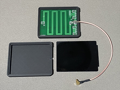
Antenna Enclosure
This enclosure was fabricated in a volume of several hundred pieces, where it was worthwhile evaluating injection molding versus 3D printing. It proved to be more cost-effective to print the body with a filament printer and laser cut the lid rather than pay for injection molding tooling. Numerous of each part were printed and laser cut at once, and there was no cleanup or other post-processing needed after printing.
3D printing also had the advantage that when a change was made to the antenna cable diameter, the enclosure could be modified for the balance of the printing run.
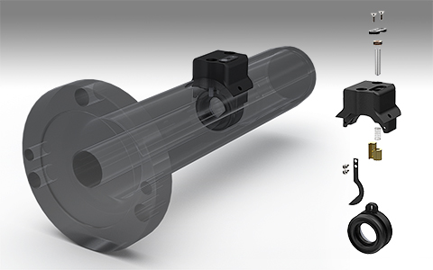
Dental Laser Shutter Retrofit Prototype
A manufacturer of dental lasers needed to upgrade the shutter in one of their products on a tight schedule, and also had severe space constraints for doing so.
Using CAD models of their existing parts and assemblies, we were able to determine the degrees of freedom that would permit a retrofit design. Complex and precise parts were CNC milled from aluminum, brass, and stainless steel, the parts were finished, and the prototype was assembled and delivered for testing.
See more information about this project at Biotech & Medical.

Mini Hugo Aboard the ISS
The Mini Hugo Rocket is a half-scale, CNC milled and hand finished aluminum version of the rocket from the Hugo trophy. The Hugo award is the science fiction and fantasy media equivalent of the Oscar.
This miniature version was commissioned by Sasquan, the 2015 World Science Fiction Convention, to be taken into space and displayed as shown aboard the International Space Station. The astronaut who carried it into space and took the photo is Kjell Lindgren.
Rapid Moldmaking for Cast Refractory Forms
Rapid Moldmaking for Cast Refractory Forms
Rapid Moldmaking for Cast Refractory Forms
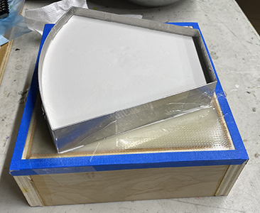
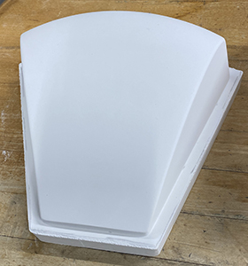
In the past, precision molds for cast refractory forms were made by CNC milling them from blocks of aluminum. The aluminum blocks were expensive, the shapes were limited by minimum tool radius and tool holder geometry, and these molds also required many hours of hand finishing inside the mold cavity to achieve the necessary surface finish. An error, mishap, or necessary change at any step of the process was costly.
A more cost-effective way to achieve results as good or even better is to use some other rapid prototyping technologies. First, the desired form is 3D printed in a high temperature polymer material. If necessary, the form can printed in multiple pieces and then assembled. See this article on assembling and finishing multi-part forms. Surface finishing on a largely convex polymer surface is much easier and faster than on a concave metal surface. The finished form is then placed into a pressure former (in many cases a vacuform machine will work too) and a sheet of plastic is pressure formed over it to create the basic mold. This formed-sheet mold is then trimmed and and fitted to a simple plywood frame. The back of the mold is then coated with a thickened epoxy in order to stiffen it and prevent any warping.
A refractory material such as a high temperature plaster mixture is then poured into the mold and allowed to cure. (Mold release compound is recommended.) As shown here, a sheet aluminum dike was added to create an additional riser base for the refractory form.